AcmeLink · Standalone centralized gateway
AcmeLink GW (B19) Centralized VRF Gateway
Control multiple indoor units with one gateway on a supported VRF system. AcmeLink GW connects to the indoor or outdoor communication bus according to the brand and model, with no additional thermostat required.
- System
- One outdoor unit + multiple indoor units
- Gateway
- One per supported system
- Connection
- Indoor or outdoor communication bus, model dependent
- Thermostat
- No additional thermostat required
One gateway, system-wide control
One outdoor unit. Multiple indoor units. One AcmeLink GW.
For the supported one-outdoor/multiple-indoor arrangement, GW controls the indoor units through the shared HVAC communication bus. A separate gateway at each indoor unit is not required for this arrangement. Confirm the bus topology and device count before ordering, especially for multiple outdoor systems or separate communication networks.
↕ Matched HVAC communication bus
One AcmeLink GW
↕ Aqara Zigbee configuration
Compatible Aqara hub → Aqara Home / supported Apple Home integration
The Aqara hub provides smart-home integration; it is not a thermostat. The gateway handles the matched HVAC bus connection.
AcmeLink series · Centralized HVAC control
AcmeLink GW (B19): VRF, fresh air and underfloor heating control
AcmeLink GW connects supported HVAC communication buses to a centralized control system. The Aqara Zigbee configuration described in this manual integrates compatible VRF air conditioning, fresh air and underfloor heating equipment with Aqara Home through a compatible hub.
Control supported power, operating mode, temperature and fan-speed functions from the app and include HVAC devices in Aqara scenes. Apple HomeKit and Siri control are described for the compatible Aqara integration; confirm the hub, destination region and required functions before ordering.
Up to 64 air conditioners
The manual specifies a maximum of 64 air-conditioning devices, 16 fresh air units and 16 underfloor heating devices. Confirm the supported equipment, bus architecture and project capacity before quotation.
Multiple HVAC brands
Brand and communication matching is configured for the actual system. The manual includes routes for Daikin, Mitsubishi Electric, Hitachi, Toshiba, Panasonic, Hisense, Haier, York, Gree, Midea, LG and other listed systems.
On-site configuration
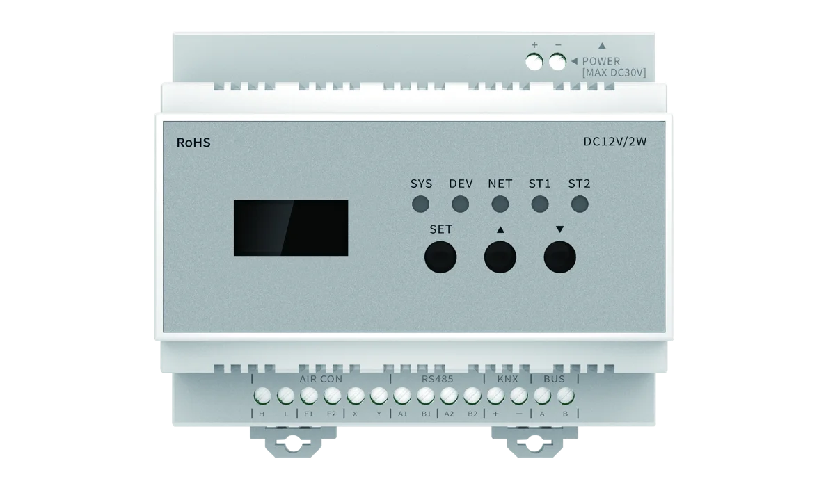
An LCD, three buttons and five status indicators assist setup and diagnosis. Bluetooth mini-program configuration and app-based database updates are described in the manual.
Product specifications
GW hardware and installation
| Model | AcmeLink_GW (B19) |
|---|---|
| Dimensions | 106 × 96 × 57 mm |
| Colour | White |
| Power supply | DC 12 V; use the supplied adapter or the approved project power supply |
| Power consumption | 2.0 W |
| Operating temperature | 0–40°C |
| Operating humidity | 0–90% RH |
| Mounting | DIN rail or concealed mounting in an accessible indoor control box or ceiling inspection location |
| Local interface | LCD; SET, UP and DOWN buttons; SYS, DEV, NET, ST1 and ST2 indicators |
| Manual-listed package | 1 controller, 1 manual and 1 DC 12 V adapter. Confirm the final project packing list. |
Specify the control configuration
The supplied manual describes Aqara Zigbee integration and identifies RS485, KNX and BUS hardware interfaces. For RS485/Modbus or KNX projects, specify the required host system and request its matching integration documentation; the presence of a terminal does not establish a particular register map, KNX application or combination of enabled functions.
WiFi and Bluetooth are described for configuration and updates. Confirm their intended role for the ordered version.
Fresh air and underfloor heating support is limited to selected brands and models. Send their exact controllers and communication information with the VRF equipment schedule.
System connection
Connect to the matched HVAC communication bus
GW provides centralized control over supported devices on a matched communication bus. Installation may use an indoor or outdoor communication connection, depending on the HVAC system. This is a different selection route from the dedicated Mitsubishi Electric CN105 AcmeLink ME module.
- AIR CON terminals: H/L, F1/F2 and X/Y, selected according to the brand and system.
- RS485 terminals: A1/B1 and A2/B2; the manual identifies fresh air and floor heating connections respectively.
- KNX terminals: + and −. Confirm the required integration documentation and ordered configuration.
- BUS terminals: A/B, described as a 485-based bus interface.
- POWER: DC 12 V socket or screw-terminal input.
Use the brand-matching tables on manual pages 7–8 with the exact indoor/outdoor model and terminal labels. Some brands have multiple routes with different polarity, addressing or external-device requirements. Have qualified personnel isolate power to the gateway and HVAC equipment before wiring and follow the model-matched instructions.
B19 technical reference
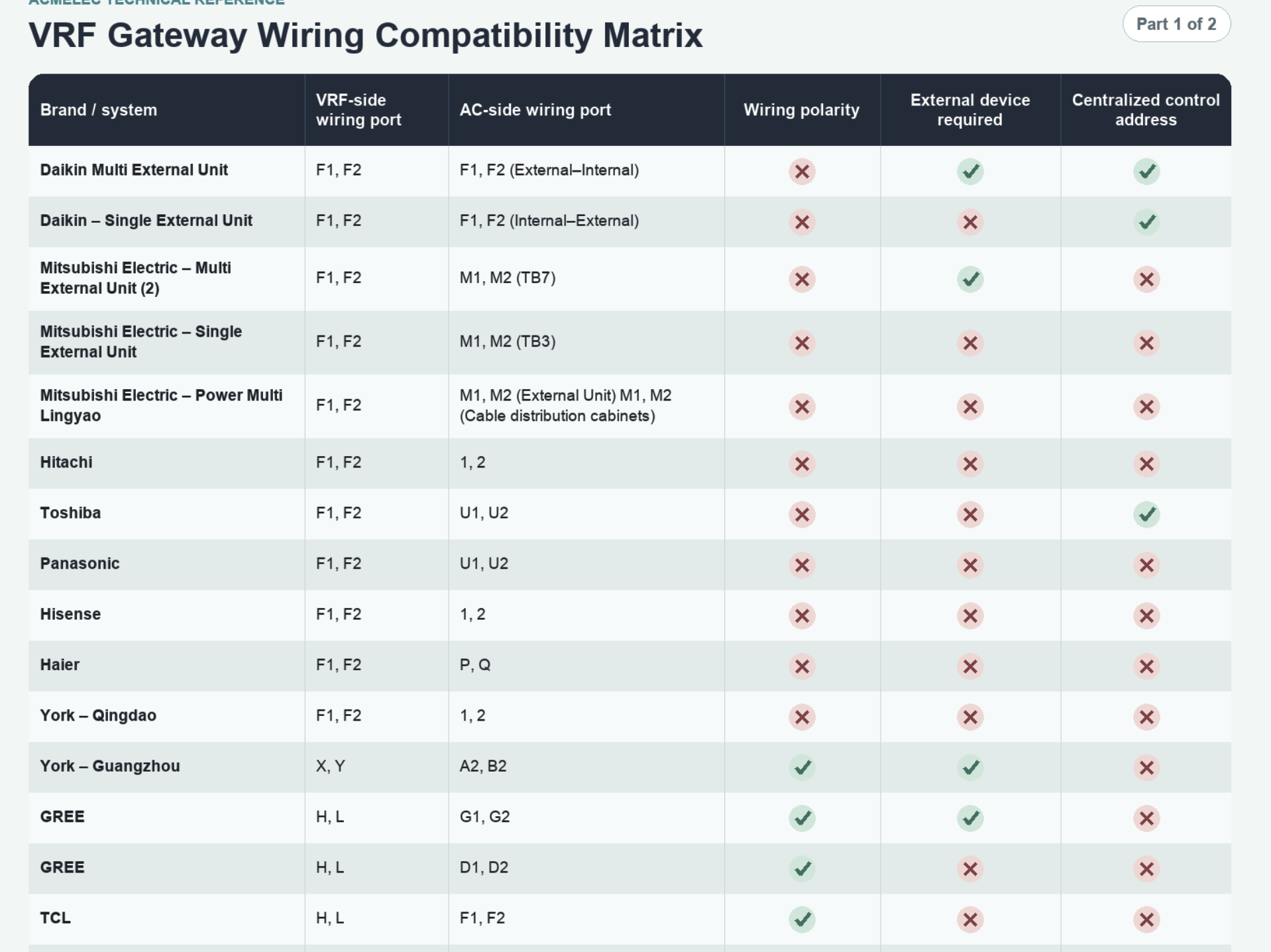
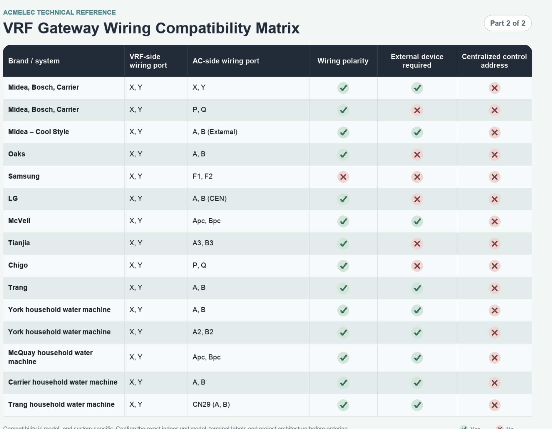
VRF gateway wiring compatibility matrix
Review Parts 1 and 2 for the listed system connection routes, wiring polarity, external-device requirements and centralized control addressing. Select each table to open the full-size image.
Compatibility is model and system specific. Confirm the complete indoor and outdoor unit models, terminal labels and project architecture before ordering or wiring.
B19 wiring reference: brands, ports and installation requirements
The text tables below reproduce the supplied reference images. Yes corresponds to a check mark and No to a cross. System names are retained as supplied; match the exact equipment and approved connection instructions before installation.
| Brand / system | VRF-side wiring port | AC-side wiring port | Wiring polarity | External device required | Centralized control address |
|---|---|---|---|---|---|
| Daikin Multi External Unit | F1, F2 | F1, F2 (External–Internal) | No | Yes | Yes |
| Daikin – Single External Unit | F1, F2 | F1, F2 (Internal–External) | No | No | Yes |
| Mitsubishi Electric – Multi External Unit (2) | F1, F2 | M1, M2 (TB7) | No | Yes | No |
| Mitsubishi Electric – Single External Unit | F1, F2 | M1, M2 (TB3) | No | No | No |
| Mitsubishi Electric – Power Multi Lingyao | F1, F2 | M1, M2 (External Unit) M1, M2 (Cable distribution cabinets) | No | No | No |
| Hitachi | F1, F2 | 1, 2 | No | No | No |
| Toshiba | F1, F2 | U1, U2 | No | No | Yes |
| Panasonic | F1, F2 | U1, U2 | No | No | No |
| Hisense | F1, F2 | 1, 2 | No | No | No |
| Haier | F1, F2 | P, Q | No | No | No |
| York – Qingdao | F1, F2 | 1, 2 | No | No | No |
| York – Guangzhou | X, Y | A2, B2 | Yes | Yes | No |
| GREE | H, L | G1, G2 | Yes | Yes | No |
| GREE | H, L | D1, D2 | Yes | No | No |
| TCL | H, L | F1, F2 | Yes | No | No |
| Brand / system | VRF-side wiring port | AC-side wiring port | Wiring polarity | External device required | Centralized control address |
|---|---|---|---|---|---|
| Midea, Bosch, Carrier | X, Y | X, Y | Yes | Yes | No |
| Midea, Bosch, Carrier | X, Y | P, Q | Yes | No | No |
| Midea – Cool Style | X, Y | A, B (External) | Yes | Yes | No |
| Oaks | X, Y | A, B | Yes | No | No |
| Samsung | X, Y | F1, F2 | No | No | No |
| LG | X, Y | A, B (CEN) | Yes | No | No |
| McVeil | X, Y | Apc, Bpc | Yes | Yes | No |
| Tianjia | X, Y | A3, B3 | Yes | No | No |
| Chigo | X, Y | P, Q | Yes | No | No |
| Trang | X, Y | A, B | Yes | Yes | No |
| York household water machine | X, Y | A, B | Yes | Yes | No |
| York household water machine | X, Y | A2, B2 | Yes | Yes | No |
| McQuay household water machine | X, Y | Apc, Bpc | Yes | Yes | No |
| Carrier household water machine | X, Y | A, B | Yes | Yes | No |
| Trang household water machine | X, Y | CN29 (A, B) | Yes | Yes | No |
For a system listed more than once, the connection route matters. For example, the supplied GREE G1/G2 route marks an external device as required, while the D1/D2 route does not. Do not select a row by brand name alone.
Send your model numbers and terminal photographs for B19 matching.
Original wiring reference images
Commissioning
Prepare the system, bind the hub and load the brand database
- Confirm the indoor/outdoor models, addresses, communication connection and any required external devices. Commission the HVAC system and resolve its alarms before adding GW.
- Connect the gateway using the confirmed wiring route and DC 12 V supply. The manual describes an initial search of approximately 2–5 minutes; compare the LCD device count with the equipment schedule.
- Add a compatible Zigbee 3.0 hub to Aqara Home. Use Add Device and search for VRF Controller, following the hub's instructions.
- Press and hold GW's SET button for about 5 seconds until the buzzer signals binding. Follow the app process to complete addition. NET green flashing indicates network search; solid green indicates successful network binding.
- For the Aqara configuration, the manual states that the factory default database supports Daikin. For another brand, open the controller's More Settings, connect WiFi, then use Update Database to select the actual air-conditioning, fresh-air or floor-heating brands.
- Allow the update and automatic restart to finish. The manual estimates about 5 minutes and describes an Upgrade Successfully message. Verify device discovery and required functions afterwards.
- Rename indoor units in the app, test commands and feedback, and verify the project scenes before handover.
Exact app labels and hub steps may vary. Confirm the current software and hub arrangement for the delivery region. Bluetooth setup is described through the “Gateway Bluetooth Configuration” mini program (网关蓝牙配网).
Status and diagnosis
Read the gateway indicators
| SYS | Slow green flashing: normal system operation. Solid green: initialization. Persistent yellow after startup: system abnormality. |
|---|---|
| DEV | Solid green: searching for units. Green flashing: units found and bus activity. Solid red: a bus fault code or no detected bus data. |
| NET | Green flashing: joining the network. Solid green: bound. Yellow: detached/offline. Red: module fault. Off: not connected or not configured. |
| ST1 | Solid green: phone Bluetooth connected. |
| ST2 | Solid green: WiFi connected. |
If discovery or control fails, provide the LCD status and fault codes, the number of expected and discovered units, brand database, unit addresses and wiring photographs. Confirm the HVAC equipment has power and no existing alarm before checking the gateway setup.
Installation resources
AcmeLink GW manual and setup references
Download English GW manual (PDF, 11 pages)
The manual includes hardware definitions, LED states, brand connection tables, Aqara binding, database updates and tutorial links. Review the instructions for the configuration you order.
B2B project matching
Request an AcmeLink GW configuration
Send the HVAC brands and complete model numbers, indoor/outdoor topology and quantities, fresh air and floor heating controller details, communication terminal photographs, desired Aqara hub or BMS/KNX system, destination country and required functions. Include sample quantity, expected rollout and OEM requirements. Pricing and configuration are confirmed through project quotation.
Discuss your AcmeLink GW project Compare the AcmeLink series
AcmeLink GW buyer questions
Does AcmeLink GW require a separate thermostat?
No. AcmeLink GW is a standalone centralized gateway that controls supported VRF equipment directly through the matched communication bus. An additional thermostat is not required for this control route.
How many gateways are needed for one outdoor unit with multiple indoor units?
For a supported system with one outdoor unit and multiple indoor units on the matched communication bus, one AcmeLink GW can provide centralized control. Confirm the system topology and device count; the manual specifies support for up to 64 air-conditioning devices.
Does GW connect to an indoor unit or the outdoor unit?
It can connect at the indoor or outdoor communication bus, depending on the HVAC brand and model. Confirm the correct terminals and connection point for the actual system.
How is AcmeLink GW different from AcmeLink ME?
GW controls multiple devices through a supported system communication bus. ME uses CN105 on a confirmed Mitsubishi Electric indoor unit. Select the gateway according to the system architecture and control requirement.
Is an Aqara hub needed?
The Aqara Zigbee configuration described in the manual uses a compatible Zigbee 3.0 hub. No additional thermostat is required, but the hub is needed for this smart-home integration route.
Can it control fresh air and underfloor heating?
The manual specifies up to 16 fresh air and 16 underfloor heating devices from selected supported brands. Confirm the exact controllers, interfaces and database before ordering.
Centralized VRF integration for multi-room projects
For villas, office zones or other projects with several indoor units on one supported VRF system, start with the equipment schedule and communication-bus layout. B19 is the centralized option when those units can be reached through the matched system bus. The gateway can connect at a supported indoor or outdoor bus connection; the correct location depends on the HVAC model.
For example, a project with one outdoor unit and eight indoor units may use one B19 when the system and bus arrangement are supported. Eight indoor units alone do not establish compatibility: separate buses, additional outdoor systems and brand-specific requirements must be reviewed.
Plan a sample before an international rollout
Send the destination country, full indoor and outdoor model numbers, unit count and terminal photographs. For Aqara projects, include the hub model and region. For BMS integration, provide the required protocol and control points so that the ordered interface and documentation can be confirmed.
Use the sample to verify discovery of every intended indoor unit, supported commands and feedback, and operation after a power restart. Record the approved wiring and configuration before repeating it across a project.
Compare centralized and single-indoor-unit VRF gateways, or see the compact B27 gateway for one indoor unit.
Model reference and gateway selection
AcmeLink_GW (B19) is also referred to as AcmeLink GW, AcmeLink B19 Gateway, AcmeLink_B19_GATEWAY. These names refer to this product route; specify the ordered configuration when requesting a sample or quotation.
Compare B19, B27, B25L, ME and DK · Read the matching B19 manual
Also consider B25L
AcmeLink B25L follows the one-gateway-per-indoor-unit approach in an 85 × 85 × 28 mm enclosure. Compare its own connector table, auxiliary output and host configuration with B27 before selecting the installation.
Documentation and source references
One gateway can serve multiple indoor units on a supported shared bus. Check system topology and the exact connection route; separate buses may require a different allocation.
Source: AcmeLink GW (B19) English manual. 11-page English manual covering the Aqara Zigbee configuration. Other integration versions require their matching documents.
- Hardware specifications and system architecture — PDF page 2
- Wiring methods and precautions — PDF page 6
- Brand connection tables (pages 7–8) — PDF page 7
Page numbers above refer to the PDF viewer. Documentation references checked on . This is a document cross-check, not a new installation test or a change to the supported-model list.
For your order, confirm the complete HVAC model, firmware, interface and required functions. How we handle technical sources and corrections.