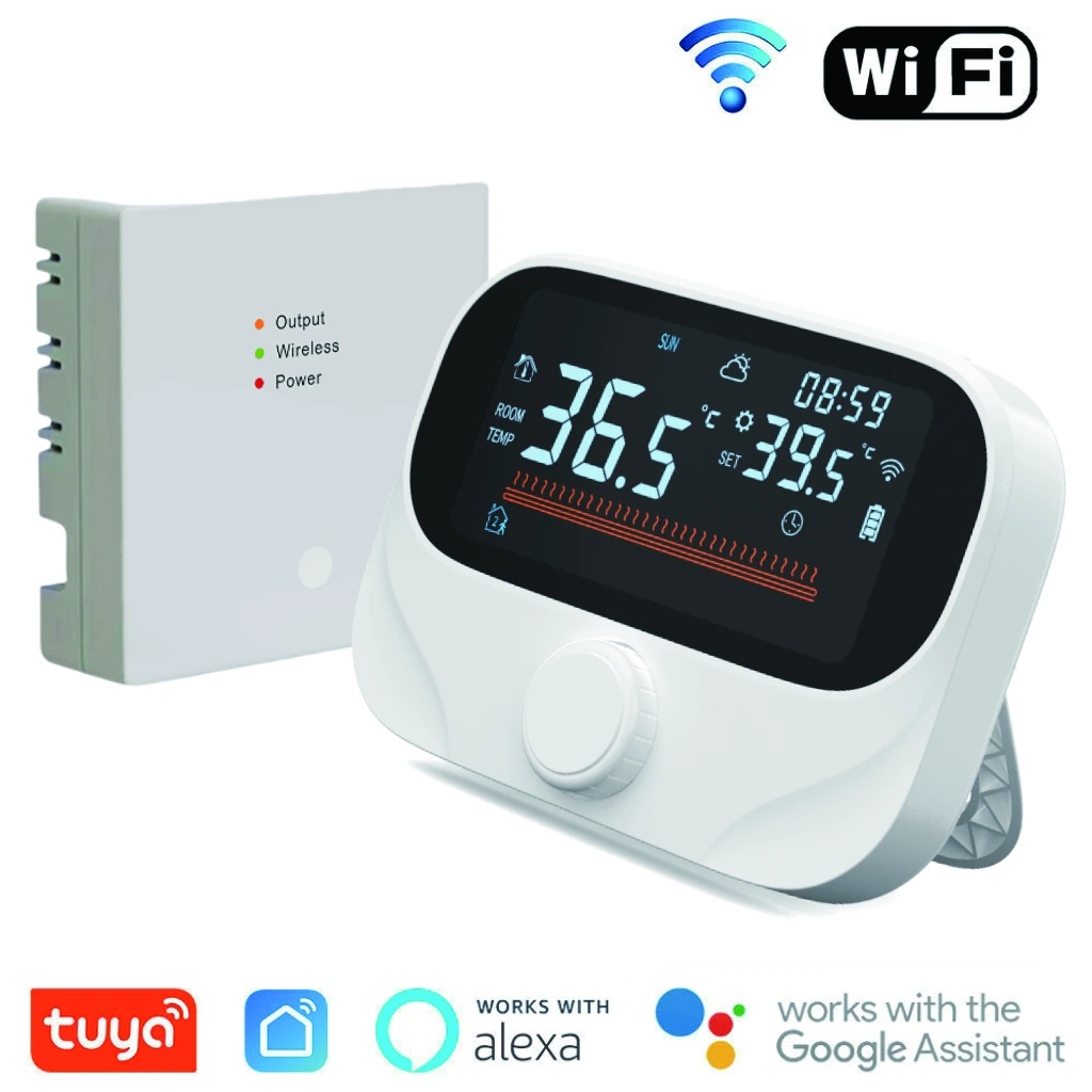
Wall-Hung Boiler Thermostat
AE-613 Wireless Wall-Hung Boiler Thermostat
AE-613-BOILER-WIFI room thermostat and receiver for compatible wall-hung gas boilers: 433 MHz RF, COM/NO dry contact, Tuya app control and weekly schedules.
Place the room panel on a desk or wall while the separate receiver connects to the boiler's compatible on/off thermostat input. Use the room panel to manage heating demand from your preferred living space.
- Model
- AE-613-BOILER-WIFI
- Room link
- 433 MHz RF
- Boiler output
- COM / NO dry contact
- Panel power
- 3 AA alkaline batteries or USB-C
Room comfort and control
Wireless placement with local and app control
Rotary temperature adjustment
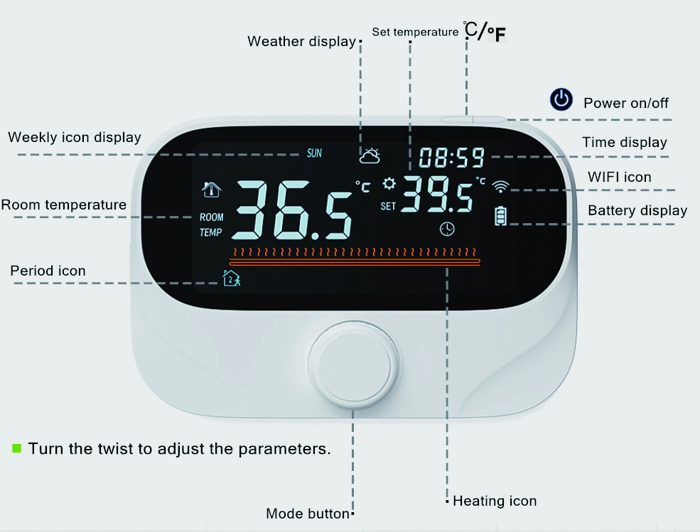
A front dial and color VA LCD provide access to room temperature, set temperature and heating status. The display also shows time, weekday and battery information.
Tuya and Smart Life
Adjust heating through Tuya Smart or Smart Life. Alexa and Google Assistant voice control require compatible services and devices. Connected weather information depends on the smart connection.
Weekly heating schedules
Choose 5+2, 6+1 or 7-day programming. The supplied details describe six workday periods and two rest-day periods with adjustable times and temperatures.
Everyday operating modes
Manual, automatic and energy-saving operation, child lock, Celsius/Fahrenheit selection and temperature memory. A temporary adjustment in automatic mode applies to the current period.
How the panel and receiver work together
- The thermostat measures room temperature at its chosen wall or desktop position.
- The room panel communicates with the separate receiver over the 433 MHz RF link.
- The receiver's COM/NO dry contact provides the heating demand signal to a compatible wall-hung gas boiler.
WiFi/app access and the RF room link serve different functions. Confirm the supplied kit, app setup and receiver arrangement before sample installation.
Check the boiler interface before ordering
Send the boiler model and thermostat-terminal diagram. Confirm that its control input accepts the proposed COM/NO dry contact; do not assume compatibility with a proprietary digital bus or OpenTherm interface.
Have a qualified installer follow both the boiler instructions and the supplied receiver wiring diagram. The receiver has a separate AC supply; the dry-contact boiler input must not be treated as a mains-powered load.
Request a compatibility checkDisplay and everyday operation
Read room temperature and heating status at a glance
The color VA LCD separates the measured room temperature from the selected target temperature. Time, weekday, the programme-period icon, heating indication, battery level and WiFi status help the user understand the current operating state. Weather information is a connected feature.
Turn the dial to adjust comfort
The front rotary dial adjusts temperature and setting values. Use the mode key to switch between manual and automatic operation. In automatic mode, changing the temperature creates a temporary adjustment for the current programme period.
- Power key: switches the thermostat on or off.
- Mode key: selects manual or automatic control.
- Short press F: switches between Celsius and Fahrenheit while the panel is on.
- Child lock: the manual describes pressing the power and mode keys together to enable or disable the lock.
Flexible room placement
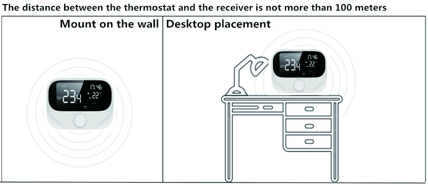
Wall mounted or placed on a desk
The separate room panel gives installers a choice of wall mounting or desktop placement. The receiver stays at the heating-system connection, while the 433 MHz link carries communication between the two parts.
For a retrofit, send the intended panel and receiver locations with the boiler model. Check RF operation at these positions before completing installation; the wireless link does not remove the receiver's power and boiler-signal wiring requirements.
Battery or USB-C power for the panel
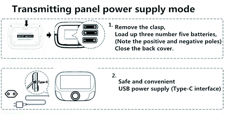
Use three AA alkaline batteries, observing the marked polarity, or power the panel through its USB-C interface. The receiver uses its own AC 90–240 V, 50/60 Hz supply. USB-C is an external supply option; the supplied information does not establish a rechargeable battery function.
Size the panel and receiver into your project
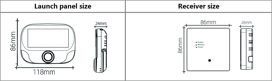
The room panel measures 118 × 86 × 24 mm (W × H × D); the receiver measures 86 × 86 × 26 mm. Check mounting space and cable access as part of the installation plan.
Programmable room heating
Choose a weekly schedule that matches occupancy
AE-613 supports 5+2, 6+1 and 7-day schedule formats. The supplied product details describe six workday periods and two rest-day periods, each with adjustable time and temperature. Choose the format and programme that match the actual household routine.
| Operating choice | How it is used |
|---|---|
| Manual | Choose a target temperature directly with the rotary control. |
| Automatic | Follow the selected heating schedule and its programmed temperatures. |
| Temporary adjustment | Turn the dial during automatic operation to adjust the current programme period. |
| Energy-saving mode | Use a dedicated temperature setting appropriate to the heating requirement. |
Set up the schedule in a practical order
- Check the displayed time and weekday. The guide states that WiFi time is obtained from the Internet when connected.
- Choose the weekly schedule format.
- Set the required period times and temperature targets using the supplied programming instructions.
- Return to automatic operation and verify the active period and target shown on the display.
- Test a temporary adjustment and confirm behaviour at the next programme period before handing over the system.
For example, a household may choose comfort settings when occupied and lower settings while away. This is a use case, not a factory-default schedule or a guaranteed energy-saving percentage. Temperature memory is listed in the product details; confirm the required restart behaviour during sample evaluation.
Smart heating control
Tuya Smart, Smart Life and compatible voice services
Use Tuya Smart or Smart Life to adjust temperature and manage heating through the supported smart connection. Amazon Alexa and Google Assistant control requires compatible services and devices. Confirm the destination market, chosen app and intended voice service before an international bulk order.
The local screen and rotary dial provide direct access to the room controls. App access, connected weather and voice integration have their own connectivity requirements. Include the required local and remote behaviour in your sample checks, especially recovery after a network interruption.
Useful project scenarios
- Residential retrofit: position the wireless panel in the living area while connecting the receiver to a compatible boiler thermostat input.
- Rental or family use: combine familiar local controls with a weekly schedule and child lock.
- Distributor selection: evaluate the display, mounting method, supplied accessories, app setup and installation literature together before agreeing a rollout.
Commissioning reference
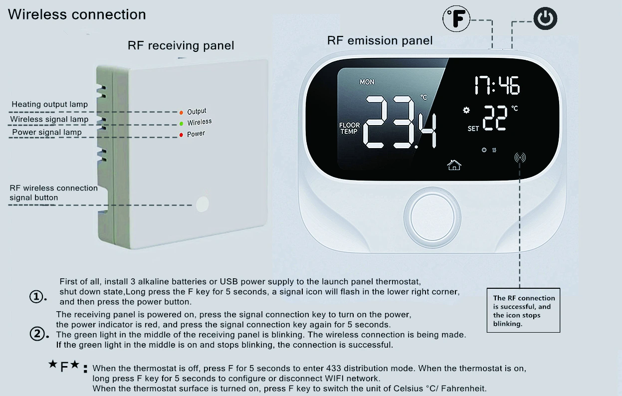
Pair the 433 MHz room panel and receiver
RF pairing links the thermostat to its receiver. It is separate from connecting the product to the WiFi app. Follow the supplied guide for the delivered hardware; receiver installation and mains wiring must be completed by qualified personnel before commissioning.
- Power the room panel with three AA alkaline batteries or USB-C.
- With the panel switched off, hold F for approximately five seconds until the signal icon flashes in the lower-right corner, then press the power key as shown in the guide.
- With the receiver safely installed and supplied with power, use its signal-connection button to turn it on; the guide identifies the power indicator as red.
- Hold the receiver signal-connection button for approximately five seconds. Its middle green wireless indicator flashes during pairing.
- Successful pairing is indicated when the green wireless light becomes steady and the panel's RF symbol stops flashing. Check heating-demand response with the installed system.
The receiver also has an output indicator. A paired radio link and a heating output are different states; check the relevant indicator when commissioning.
WiFi setup uses a different panel state
With the room panel on, the manual describes holding F to configure or disconnect WiFi and a three-minute configuration window. Use the matching app instructions for the supplied version. Do not repeat the panel-off RF sequence when the intended task is WiFi setup.
If setup does not complete
- No panel display: check battery polarity and supply, or the USB-C power connection.
- RF indicator keeps flashing: check receiver power, pairing state, separation and obstructions; repeat the matched RF procedure.
- RF paired but heating does not respond: ask the installer to verify the selected mode, target temperature and boiler control interface.
- App connection incomplete: confirm WiFi setup mode and the app instructions for the delivered version. Provide the indicator state and app message when requesting support.
Receiver mounting and boiler wiring checks
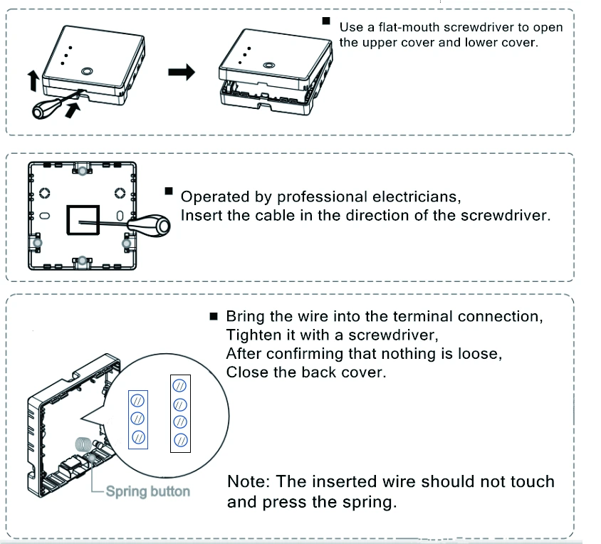
The supplied mounting illustration shows opening the receiver enclosure, bringing the cable into the terminals and securing the cover after checking the connections. Installation must be performed with power isolated by qualified personnel.
For the wall-hung boiler application, confirm COM and NO against the boiler's thermostat input diagram. The manual also illustrates NC and other load terminals; these do not establish suitability for every heating load. Confirm the exact supplied receiver and required application before wiring.
Send a clear boiler terminal diagram with the enquiry so the control route can be checked before ordering. For a digital control bus, request a separate compatibility assessment.
AE-613 buyer questions
Do I need to run a signal cable from the room panel to the boiler?
The room panel communicates wirelessly with its receiver over 433 MHz. The receiver still requires its own supply and the correct boiler-signal wiring.
Does USB-C charge the AA batteries?
The supplied information lists AA alkaline batteries or USB-C external power. It does not specify a charging function. Treat these as the stated supply options.
Is the 300 m range guaranteed inside a building?
No. Up to 300 m is the specification statement; the installation guidance recommends within 100 m. Walls and the installation environment affect the working link.
What should I test before ordering in volume?
Verify the boiler input, panel and receiver power, RF coverage, app connection, required voice service, schedule transitions, child lock and the required restart behaviour with the exact sample.
Thermostat panel specifications
| Dimensions (W × H × D) | 118 × 86 × 24 mm |
|---|---|
| Power | 3 AA alkaline batteries / USB-C |
| Setting range | 5–60 °C |
| Listed control accuracy | 0.1 °C, as stated in supplied specifications |
| Display | Color VA LCD |
| Placement | Wall mounting or desktop |
Receiver and shared specifications
| Receiver dimensions | 86 × 86 × 26 mm |
|---|---|
| Receiver supply | AC 90–240 V, 50/60 Hz |
| Listed load current | 3 A; confirm the exact output and load |
| Boiler connection | COM / NO dry contact |
| RF frequency | 433 MHz |
| Operating temperature | 5–50 °C |
| Housing / protection | Flame-retardant PC/ABS V0 / IP20 |
| Listed consumption | 1 W per unit |
RF distance and installation planning
The specifications state an RF distance of up to 300 m, while the installation guidance recommends keeping the thermostat within 100 m of the receiver. Walls, building layout and interference affect performance; verify the link at the intended installation positions before rollout.
The 3 A specification and COM/NO boiler connection describe the selection information used here. Other load connections shown in the manual require confirmation for the supplied receiver; this listing does not establish a 16 A electric-heating rating.
English documents and package
The listed package includes the thermostat and receiver, signal cable, USB cable, mounting screws, product certificate and user guide. Confirm supplied accessories and battery inclusion with the quotation.
The product details contain five pages; the user guide is a single long-format page. Use the wiring instructions matched to the delivered receiver.
Prepare a sample or bulk enquiry
- Boiler make, full model and control-terminal diagram.
- Room panel position, receiver position and RF separation.
- Destination country and required compliance documents.
- Sample quantity, bulk quantity and requested schedule.
- App, voice service, packaging and manual-language requirements.
Price, configuration, sample availability and supply terms are confirmed through B2B quotation.
Request Product InformationCompare wall-hung boiler control options
Browse wall-hung boiler thermostats or read the boiler thermostat selection guide to compare installation and interface requirements.